How Did Ancient Aqueducts Work? Gravity, Slope & Stone
To understand how did ancient aqueducts work, picture a riverbed so gently tilted that water creeps along it for a hundred kilometres, never once being pumped — pulled the entire way by the patient pressure of gravity. No engines. No electricity. Just stone, mortar, geometry, and a slope so subtle that a modern surveyor would struggle to draw it.
Key Facts
- The world’s first long-distance aqueducts were not Roman but Persian: the qanat, an underground tunnel system, was developed in Iran in the early 1st millennium BCE — roughly 3,000 years ago.
- Rome’s first aqueduct, the Aqua Appia (begun 312 BCE under censor Appius Claudius Caecus), ran 16.6 km from spring to city and dropped only 10 metres over its entire length.
- By the imperial era, eleven aqueducts delivered close to 1 million cubic metres of water to Rome every day — supplying roughly 1,200 public fountains and nearly 900 baths.
- The famous Aqua Marcia maintained an average gradient of about 1 part in 3,000 — a drop of just 33 centimetres for every kilometre of channel.
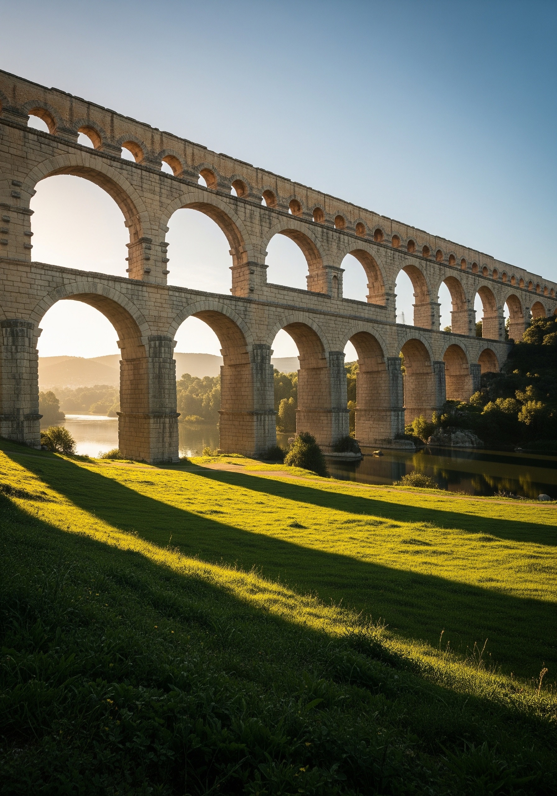
- The Pont du Gard in southern France rises 49 metres above the Gardon river in three tiers of arches, carrying a water channel that fell only 17 metres across the entire 50 km route from its springs to Nemausus (modern Nîmes).
In short: Ancient aqueducts moved water from a higher source to a lower city using a single force — gravity — channeled along an extraordinarily precise downward slope. The engineering was not in lifting water but in not losing it: building tunnels, bridges, and inverted siphons that preserved a fall measured in centimetres per kilometre across some of the most rugged terrain in the ancient world.
Key Facts
- The world’s first long-distance aqueducts were not Roman but Persian: the qanat underground tunnel system was developed in Iran in the early 1st millennium BCE, roughly 3,000 years ago.
- Rome’s first aqueduct, the Aqua Appia (begun 312 BCE under censor Appius Claudius Caecus), ran 16.6 km from spring to city and dropped only 10 metres over its entire length.
- By the imperial era, eleven aqueducts delivered close to 1 million cubic metres of water to Rome every day, supplying roughly 1,200 public fountains and nearly 900 baths.
- The Aqua Marcia maintained an average gradient of about 1 part in 3,000, a drop of just 33 centimetres for every kilometre of channel.
- The Pont du Gard in southern France rises 49 metres above the Gardon river in three tiers of arches, carrying a channel that fell only 17 metres across the entire 50 km route to Nîmes.
In short: Ancient aqueducts moved water from a higher source to a lower city using gravity alone, channeled along an extraordinarily precise downward slope measured in centimetres per kilometre. The engineering challenge was not lifting water but not losing it, achieved through tunnels, bridges, and inverted siphons across rugged terrain. The Persians pioneered the underground qanat centuries before Rome’s first aqueduct, and Roman surveyors held their gradients using a tool called the chorobates.
The simplest idea, the boldest execution
An aqueduct is, at heart, an artificial river. It begins at a spring, a lake, or a mountain stream that sits higher than the city it serves. Then — through tunnels bored through hillsides, masonry channels following the contour of the land, and stone bridges leaping across valleys — the water is coaxed downhill, slowly and continuously, until it pours out of a fountain in a public square.
What separates an aqueduct from a ditch is precision. Ditches let water rush; aqueducts make it walk. A channel that falls too steeply will scour its own lining and arrive empty; one that falls too gently will silt up and stagnate. The genius of ancient water engineering lies in finding — and maintaining, across dozens of kilometres — the impossibly fine middle ground.
Before Rome: the Persian qanat
Roman aqueducts are the icons, but they were not the first. Six centuries before the Aqua Appia broke ground, engineers on the Iranian plateau had already solved the problem of moving water across arid landscapes — they just did it underground.
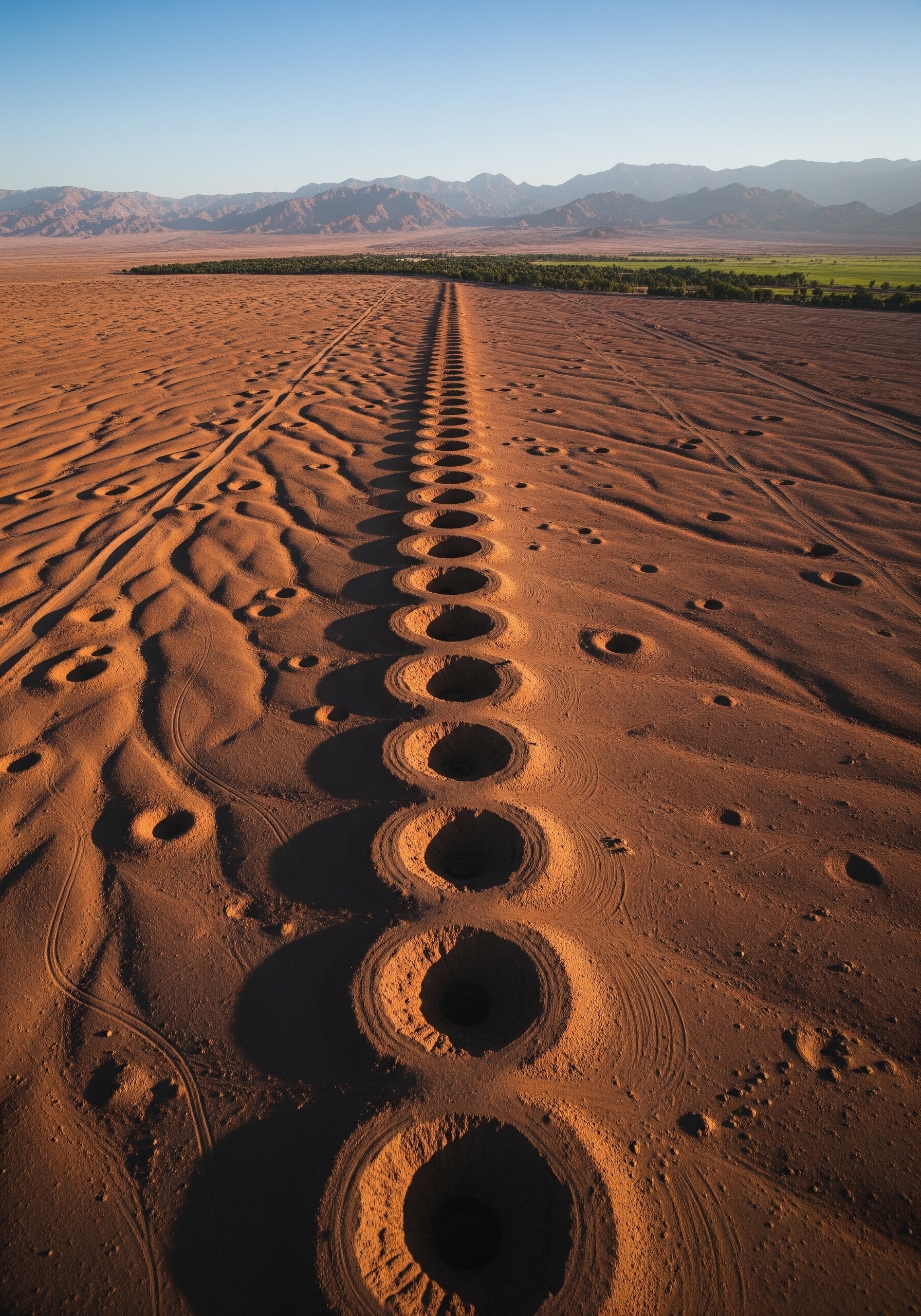
The Persian qanat, developed in the early 1st millennium BCE and perfected under the Achaemenid Empire (c. 550–330 BCE), is a gently sloped tunnel hand-dug into an alluvial fan or hillside. At its upstream end, deep inside the slope, it intercepts the groundwater table. From there it runs at a careful gradient for kilometres — sometimes tens of kilometres — until it surfaces near a field or settlement. A line of vertical shafts above the tunnel, visible from the air as a row of small craters, provided ventilation during construction and access for cleaning afterwards.
{IMAGE_2}
Qanats are still in use today across Iran, Oman, Afghanistan, and beyond, and UNESCO inscribed a network of the most ancient examples on the World Heritage list. Their advantage over Roman-style aqueducts is shade: by running underground, they avoided the evaporation losses that would have crippled an open channel in a desert climate. According to the World History Encyclopedia, Persian qanat technology was later adopted in Egypt under Darius I and eventually spread along trade routes into Central Asia, North Africa, and even Roman territories — meaning the Romans, far from inventing the long-distance aqueduct, inherited a much older tradition.
How did ancient aqueducts work? The physics of gravity flow
Strip away the masonry and the answer is geometry. An aqueduct is a long, slightly tilted channel — usually rectangular in cross-section, lined with waterproof concrete or clay — in which water flows because one end is higher than the other.
The crucial number is the hydraulic gradient: the vertical drop per unit of horizontal length. Roman engineers aimed for gradients between roughly 1:200 and 1:5,000 depending on terrain, with most main lines settling between about 1:2,000 and 1:5,000. The Aqua Marcia, completed in 144 BCE, averaged close to 1 in 3,000 — meaning the channel fell about 33 centimetres for every kilometre. That is less than the height of a paperback book over the length of ten football pitches.
Why so gentle? Faster flow erodes the channel’s lining and undermines the bridges and tunnels carrying it. Slower flow allows sediment to settle, mineral deposits to build up, and biological growth to clog the works. The compromise: an open-channel velocity typically around 1 to 1.5 metres per second — a brisk walking pace — sustained for as long as a hundred kilometres without interruption.
Building the slope: surveying with the chorobates
Holding a gradient of 33 centimetres per kilometre across mountainous country requires a survey that is, in modern terms, nearly impossible without a laser level. Roman engineers had no such tools. They had the chorobates.
The chorobates was a six-metre-long wooden plank fitted with vertical legs, plumb-bobs, and a shallow water-filled trough cut into the top surface. When the trough’s water settled flat, the plank itself was perfectly level. By aligning sight lines across successive chorobates positions and recording the differences with measuring rods, Roman mensores could plot a route from spring to city with a vertical precision of a few centimetres over kilometres. Auxiliary tools — the groma for right angles, the dioptra (Greek in origin) for more complex sightings — handled the harder geometry.
This is why surviving aqueduct channels, when archaeologists trace them today, follow such peculiar paths. They detour around hills, hug contours, and loop kilometres out of their way. Every metre of horizontal travel is a metre that did not waste vertical drop. The route is the calculation, frozen in stone.
Bridges and inverted siphons: crossing valleys
Most of any Roman aqueduct ran underground or on low masonry walls — not on the towering arches that dominate the imagination. The Aqua Appia, Rome’s first, was about 99 percent subterranean. Only when the terrain dropped away faster than the channel could afford did engineers reach for two more dramatic solutions.
The first was the arched bridge. Where a valley was wide and shallow, builders threw a row of stone arches across it, sometimes stacking arches in two or three tiers to gain height. The Pont du Gard, part of the Nemausus aqueduct in southern Gaul, is the most famous survivor: a three-level structure rising 49 metres above the Gardon river, carrying the water channel along its top tier. Across the entire 50-kilometre Nîmes line, the engineers had to spend their vertical budget — barely 17 metres of total drop — with breathtaking care.
The second solution, used where valleys were too deep or steep for any plausible bridge, was the inverted siphon. Despite the name, this is not a siphon in the modern physics sense. The water entered a sealed pressure-rated conduit — usually made of lead pipes, sometimes stone blocks bored through and sealed — at one side of the valley, descended through a header tank, plunged to the valley floor, and rose again on the far side to a receiving tank set slightly lower than the inlet. The pressure of the descending water column drove the rise, in the same way a U-bend equalises levels in a household tap. Some Roman siphons, like the one at Lyon (ancient Lugdunum), descended more than 120 metres and operated at internal pressures that would have torn apart anything less than carefully fitted lead.
Anatomy of a Roman aqueduct, in numbers
- Source: a spring, lake, or river upstream and uphill of the city.
- Channel cross-section: typically 0.5–1.2 m wide, 1.5–2.5 m tall, lined with hydraulic concrete (opus signinum).
- Average gradient: 1:2,000 to 1:5,000 (≈ 20–50 cm of fall per km).
- Flow velocity: roughly 1.0–1.5 m/s — a steady walking pace.
- Daily delivery to Rome at imperial peak: ≈ 1,000,000 m³ from 11 aqueducts combined.
- Coverage: ≈ 1,200 public fountains and 900+ baths supplied by these flows.
From source to spigot: the castellum and Rome’s distribution network
The aqueduct ended, but the water’s journey did not. As the channel approached the city, it ran into a castellum aquae — a large stone distribution tank, usually built on the highest convenient ground inside the walls. The castellum acted as both reservoir and pressure regulator: incoming water filled it, sediment settled to the bottom, and a row of outlet pipes drew off the supply at controlled heights.
From the main castellum, water flowed by gravity to secondary tanks (castella secundaria) scattered across the city’s neighbourhoods, then through smaller lead pipes (fistulae) into the public fountains where most Romans collected their water, into the imperial baths, and — for the privileged few who could afford the licence fee — directly into private homes. Stopcocks, mesh filters, and settling basins were spliced into the network. Where water ran particularly hard or warm, engineers sometimes aerated it through small cascades to freshen the taste.
The hierarchy was deliberate. Public fountains had legal priority; baths came next; private taps were last. If a drought reduced the flow, the law required private licences to be cut off first so that the public supply continued. It was, in the dry phrase of the modern hydraulic engineer, the world’s earliest documented potable-water rationing protocol.
The greatest aqueducts of the ancient world
Roman builders eventually erected over 1,600 km of aqueducts across an empire stretching from Britain to Syria. Not all were colossi. A handful, though, became benchmarks of what gravity-fed engineering could achieve.
| Aqueduct | Built | Length | Notable for |
|---|---|---|---|
| Persian qanats (Iran) | c. 1000–500 BCE | Often 10–40 km each; tens of thousands across Iran | Underground groundwater tunnels; still used today. |
| Aqua Appia (Rome) | 312 BCE | 16.6 km, ~99% underground | Rome’s first; only 10 m of vertical drop. |
| Aqua Marcia (Rome) | 144 BCE | ≈ 91 km | Famed for cold, pure water; gradient ~1:3,000. |
| Pont du Gard / Nîmes line | 1st century CE | ≈ 50 km | 49 m three-tier bridge; total fall only ~17 m. |
| Aqueduct of Segovia (Spain) | 1st–2nd century CE | ≈ 17 km; arcade 813 m long | Mortarless granite, still standing. |
| Aqueduct of Constantinople | 4th century CE | Over 250 km of channels in total | Longest known ancient water network by combined length. |
Beyond Rome’s frontier, the principle of gravity-fed water carriage appeared independently in other civilisations: the Greeks at Samos drove the famous Tunnel of Eupalinos through a mountain in the 6th century BCE; the Maya built sealed pressurised conduits at Palenque; the Inca terraced and channelled mountain springs across the Andes at Tipón and elsewhere. The instinct to deliver clean water by tilt and tunnel is one of the most universal ideas in human engineering.
Why ancient aqueducts still matter
Modern cities pump. Pressurised mains, electric pumps, and treatment plants do almost all of the heavy lifting that gravity used to do alone. But the underlying architecture — a remote source, a long-distance conveyance, a city-side reservoir, and a hierarchical distribution network of mains and lesser pipes — is unmistakably the Roman model, refined.
The U.S. Geological Survey points out that California’s modern aqueduct system, which carries water hundreds of kilometres from the Sierra Nevada and Colorado River to Los Angeles and the Central Valley, still relies on gravity for much of its journey, supplemented by pumps only where the terrain demands a lift. The Central Arizona Project, the New York City water tunnels, and the great urban supplies of Europe all share the basic Roman insight: that the cheapest way to move a river is to let it flow.
When archaeologists trace a Roman channel through a Spanish hillside or peer down the ventilation shafts of an Iranian qanat, what they are uncovering is not just a relic. It is a working diagram of urban civilisation itself — the first technology that made dense, sanitary, year-round city life possible.
Frequently Asked Questions
Q: Did Roman aqueducts really work entirely on gravity, with no pumps?
A: Yes. The main-line conveyance was 100% gravity-driven. Roman engineers knew about pumps — the Ctesibian force pump and the Archimedean screw were both familiar to them — but they used these for draining mines, firefighting, and bilge work, not for raising drinking water. The aqueduct’s slope did the work.
Q: How did the Romans calculate such a tiny gradient over such long distances?
A: With the chorobates, a six-metre wooden levelling plank that used either a trough of still water or a series of plumb-bobs to establish a horizontal reference. Combined with sighting rods and the dioptra, surveyors could measure vertical drops of a few centimetres over hundreds of metres — enough to plot a 1:3,000 gradient across kilometres of broken terrain.
Q: Who invented aqueducts — the Romans or someone earlier?
A: Long-distance water conveyance is much older than Rome. The Persian qanat dates from the early 1st millennium BCE, about 600 years before the Aqua Appia. The Assyrian king Sennacherib built a stone aqueduct at Jerwan around 690 BCE to supply Nineveh. The Romans inherited the idea and industrialised it, building it bigger, faster, and across an entire empire.
Q: How clean was aqueduct water by modern standards?
A: Often surprisingly clean — Roman engineers chose cold mountain springs precisely because the water arrived already filtered through limestone — but not safe by modern standards. Lead distribution pipes added contamination, sediment built up in channels, and biological contamination was a constant risk. Public fountains were typically safer than private taps, because they flushed continuously.
The next time you turn on a tap, spare a thought for the unnamed Roman mensor who, two thousand years ago, walked the same kind of distance from source to settlement with a wooden levelling plank, plotting a slope of thirty-three centimetres per kilometre. The technology has changed beyond recognition. The geometry has not.
Illustrations are AI-generated. Article fact-checked and human-edited.